 SAMPLED
Sync your analog gear: clock, DIN, and drift
Master clock choices, why your machine rushes the downbeat, and how to fix timing at the source.
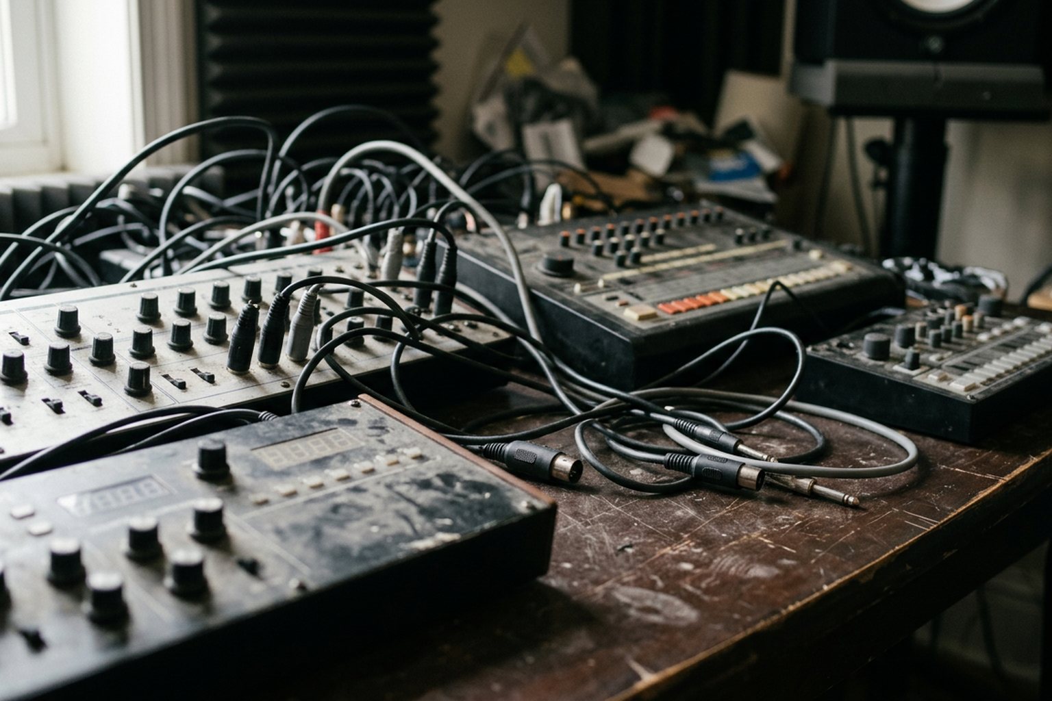
A hardware setup with slightly off-kilter timing destroys a groove faster than a poorly tuned synth patch. When your drum machine rushes the downbeat and your arpeggiator drags behind the grid, the culprit is rarely human error or faulty sequence programming. It is almost always a fundamental mismatch in how your gear receives, interprets, and calculates clock signals.
The Anatomy of Sync Protocols
To solve timing issues in a mixed hardware studio, you need to understand the different languages machines use to stay in time. Not all clock signals carry the same information, and mixing protocols without accounting for their translation delays leads directly to phase cancellation and muddy rhythms.
Analog Pulse and Trigger Sync
Analog clock is the simplest sync method available. It uses raw control voltage (CV) pulses sent over standard patch cables to advance a step sequencer or arpeggiator. Every time the receiving unit detects a voltage spike (typically five volts), it moves forward one step.
Because analog pulse sync carries no digital header, data bytes, or channel routing, it has virtually zero propagation delay. However, pulse density standards vary by manufacturer. Simple desktop units and modular gear often expect 1 PPQN (pulse per quarter note) or 2 PPQN, while Korg Volca units and modern desktop synths typically operate at 2 PPQN. Other standards use 24 or 48 pulses per quarter note. If your master clock sends 24 pulses to a unit expecting 2, the receiving sequencer will play twelve times too fast.
DIN Sync (Sync24 and Sync48)
Developed by Roland before the adoption of MIDI, DIN Sync uses a standard 5-pin DIN cable, but the signal path inside is entirely analog. Unlike MIDI, which sends serial data down a single line, DIN Sync isolates functions onto dedicated pins within the cable. Pin 1 carries a continuous start/stop voltage (high voltage for run, zero volts for stop), pin 3 carries the clock pulses, and pin 2 acts as the ground connection.
The most common implementation is Sync24, which transmits 24 clock pulses per quarter note. Roland classics like the TR-808, TR-606, and TB-303 rely on this format. Other manufacturers, such as Korg with their early drum machines, used Sync48, which doubles the pulse density. Because DIN Sync relies on direct electrical state changes rather than software byte processing, it offers exceptionally tight phase locking between vintage machines.
5-Pin MIDI Clock
Introduced in 1983, MIDI Clock transmits timing data digitally over standard 5-pin cables at a fixed resolution of 24 PPQN. The protocol sends discrete status bytes: Timing Clock (hexadecimal F8), Start (FA), Continue (FB), and Stop (FC).
Because MIDI Clock shares a single serial cable with note numbers, pitch bend, velocity, and continuous controller data, bandwidth congestion can occur. If a sequencer blasts dense parameter automation down the same cable at the exact moment a timing byte needs to transmit, the clock byte gets delayed. This micro-delay manifests as subtle timing instability.
USB MIDI Clock
USB MIDI is the primary source of timing headaches in hybrid studio setups. Standard 5-pin MIDI transmits serial data at a fixed rate. USB, on the other hand, packages data into buffers managed by the computer operating system's CPU scheduler.
Because operating systems prioritize background tasks, graphics, and audio processing dynamically, USB MIDI clock bytes are delivered in uneven clusters. The computer sends a burst of clock bytes, pauses briefly to handle an OS process, and then sends another burst to catch up. Hardware sequencers slaved to USB MIDI try to calculate the average tempo between incoming pulses, resulting in constantly shifting tempo displays and audible groove jitter.
Hardware Sync Protocols Compared
| Protocol | Signal Type | Standard Resolution | Primary Cause of Timing Failure |
|---|---|---|---|
| Analog Pulse | Continuous CV Voltage | 1, 2, 24, or 48 PPQN | PPQN mismatch causing high-speed or slow playback |
| DIN Sync | Discrete Analog Pins | 24 PPQN (Sync24) or 48 PPQN | Faulty cable wiring or start/stop voltage drop |
| 5-Pin MIDI Clock | Digital Serial Bytes | 24 PPQN | MIDI bandwidth saturation from heavy CC data |
| USB MIDI Clock | Operating System Packets | Variable / 24 PPQN target | Host CPU scheduling and USB buffer jitter |
Why Your Hardware Rushes, Drags, or Fluctuates
Fixing hardware sync requires distinguishing between two distinct timing anomalies: latency and jitter.
Latency Versus Jitter
Latency is a constant, static time offset. If your drum machine plays precisely fifteen milliseconds behind the DAW grid every single bar, you have a latency issue. Latency is easy to resolve. You simply apply a negative track delay in your host software or adjust the hardware buffer offset until the audio aligns with the grid.
Jitter is dynamic, unpredictable variance. If your hardware rushes the first beat of bar one, lags on bar two, and locks correctly on bar three, you are dealing with clock jitter. You cannot fix jitter with static delay compensation because the offset changes constantly. Jitter destroys the micro-timing of drum patterns, causing kick drums to phase against sample layers and ruining the feel of an analog groove.
Swing and Shuffle Mismatches
Timing discrepancies also occur when combining hardware with differing swing implementations. Vintage drum machines like the Roland TR-909 or LinnDrum achieve swing by delaying every second sixteenth note at the internal sequencer level. Modern DAWs and hardware sequencers accomplish this by altering the timing of the emitted clock pulses themselves.
If your master device emits a clock that already contains swing, and you feed that clock into a slave unit with its own internal swing setting enabled, the slave unit will double-apply the timing shift. The result is an unnatural, stumbling rhythm where offbeats drag far too late into the measure.
Fixing Timing at the Source
To eliminate jitter and maintain tight hardware synchronization, you must bypass the unstable USB timing stack and establish a clean master-slave hierarchy.
Bypassing USB with Audio-Derived Clocking
The most reliable method for locking a computer DAW to external hardware is audio-derived clocking. Unlike USB MIDI data, audio streams receive top priority from your computer audio driver and operating system. Audio sample playback is locked to the audio interface clock crystal, which exhibits negligible jitter.
By generating a sharp, high-amplitude audio pulse (such as a short square wave click) inside your DAW, you can route an audio signal out of an unused channel on your audio interface. Running this audio cable into an audio-to-clock converter or directly into the analog pulse sync input of a hardware synthesizer turns your DAW audio engine into a stable hardware master clock.
Using Dedicated Hardware Master Clocks
If you perform entirely without a computer, or if you want an external hardware box to control your whole studio, use a dedicated hardware master clock generator. Devices designed specifically for clock translation take an incoming audio pulse or internally generated clock and split it into multiple isolated outputs.
These units offer dedicated hardware knobs for individual port latency, micro-offset, and phase alignment. By placing a hardware clock converter between your audio source and your synths, you can send frame-accurate 5-pin MIDI clock, DIN Sync24, and analog triggers simultaneously without relying on software timing.
Establishing Correct Signal Distribution
Never daisy-chain more than two or three hardware units using MIDI Thru ports. Every hardware device in a chain introduces a small amount of optocoupler latency and edge-degradation to the digital signal. By the fourth or fifth machine in a daisy chain, the sharp edges of the MIDI data degrade, causing dropped clock bytes and timing drift.
Instead, use a star-topology layout. Run your master clock into an active, powered MIDI Thru box or clock splitter. This sends an identical, parallel clock signal to every synth and drum machine simultaneously, guaranteeing that every instrument receives its timing pulse at the exact same instant.
Quick Answers
Why does my drum machine start a fraction of a beat late when receiving MIDI clock?
Hardware sequencers require a moment to process incoming MIDI Start commands and calculate tempo from incoming clock bytes. If the master device transmits the Start command at the exact microsecond as the first clock pulse, the slave unit may miss the initial beat. Sending a continuous clock signal or enabling a pre-roll delay on your master sequencer gives slave devices time to lock onto the tempo before playback begins.
Can I convert DIN sync to standard MIDI clock with a simple passive adapter cable?
No. Although DIN Sync and MIDI use identical 5-pin DIN connectors, their electrical wiring and signaling protocols are entirely incompatible. DIN Sync relies on raw continuous voltages, while MIDI uses high-speed digital serial data. You must use an active hardware converter to translate analog DIN Sync pulses into digital MIDI clock bytes.
What is the difference between clock jitter and clock latency?
Clock latency is a constant time offset where events are delayed by a fixed, repeatable duration. Clock jitter is erratic, real-time fluctuation in timing where the time gap between consecutive clock pulses constantly varies. Latency can be corrected with fixed offset controls, whereas jitter requires changing the master clock generation source.
How do I sync modern Eurorack modular gear to vintage analog synthesizers?
Eurorack systems use analog gate and trigger pulses, while vintage synths often require DIN Sync24 or standard 5-pin MIDI clock. To bridge them, use a dedicated utility module or hardware converter capable of transforming incoming gate triggers into DIN Sync or MIDI clock bytes. Ensure the PPQN output resolution selected on the converter matches the input requirements of your vintage synth.
Audit your hardware setup before your next recording session. Trace every sync line back to its point of origin, eliminate USB MIDI clock distribution to external hardware, and route your clock through active distribution splitters. Once your hardware rig operates on a unified, low-jitter clocking hierarchy, your sequences will lock together with absolute clarity and impactful micro-timing.